Posted on

Various sources for the sensors

MPXV6115VC6U
MPXV6115VC6U

Please note: COVID-19 has made many parts less available. Most suppliers are indicating that new sensors will be available soon. The new good news is I was able to use the OpenAI artificial intelligence engine online to identify substitute parts that were available. This post has been updated to include more potential part numbers. I’ve also added some links for those who can order directly from China.

The sensors are the most expensive part. The price varies between suppliers. They regularly go on sale. There are odd lots available, even on eBay. Sometimes they are much cheaper to buy on a piece of tape roll than on a rail (these are different automated assembly techniques) or vice versa. Some substitutes work just as well. Make 2 or three boards or go together with friends – the more you can buy, the cheaper they get.

Start with a search on ‘MPXV6115VC6U’. This is the standard sensor in the bill of materials. Search on some of the other part numbers, too.

Sometimes these parts are available, but ensure that you are ordering a sensor with a top port – MPXV5050VC6T1,  MPXV4115VC6U,  MPXV6115VC7T.

Shop around. Below are links to a few examples. The board can be set to run on either 5v or 3.3v sensors.

Here’s a search engine that can sometimes find things: http://www.findchips.com/

Another search engine that can be very useful is https://octopart.com/search?q=MPXV6115VC6U.

Another search engine: https://www.eciaauthorized.com/en/search/MPXV6115VC6U

Another search engine: https://www.onlinecomponents.com/

If you can order directly from China, here are a couple of links to get you started. These usually have the lowest price:

Alibaba

Shenzhen Xinzhongtai Electronic Technology Co., Ltd.

Contact us if you find something new, and we’ll check it out. Here are the basics.

You need a vacuum sensor for each cylinder. It should measure vacuum from approximately negative 7 to 10 pounds per square inch up to zero vacuum. Or, if measured in kPa,  negative 60 to 115 kPa up to at least zero vacuum. The part shown in the picture measures -115 kPa to 0. Most bikes will idle and rev in the 7 to 10 lbs per square inch range of vacuum.

It should be in a standard SOM package, with a port, either smooth or barbed. See the picture with a smooth port and 8 ‘legs’.

It should run on either 5 volts or 3.3 volts. These are standard. The board can be built for either. Sometimes a range around the voltage value is advertised in the sensor specs. For example, a spec might say input voltage 2.2 to 4.6 volts instead of just saying 3.3v.

It should output analog voltage, zero through up to approximately 5 volts.

If you find something, compare the spec sheet to the spec sheets of the options below, especially the Digikey. Use the standard sensor from Digikey unless you find something at a great price.

Digikey.com

Mouser.com

Newark.com

Mouser.com 3.3v build option

AVNET.com 3.3v build option

Last updated 12/31/2022

Posted on

Why build your own digital carb sync tool?

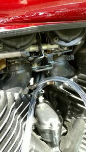
You need to keep your carburetors synchronized

Is the performance of your old motorcycle or other multi-carburetor engine lagging? Synchronize the carburetors regularly so the cylinders aren’t working against each other.

Are you tired of the mess and fuss of oil-filled plastic tubes? Mercury manometers are great if you have one, but they are fragile, toxic, and no longer available for purchase.

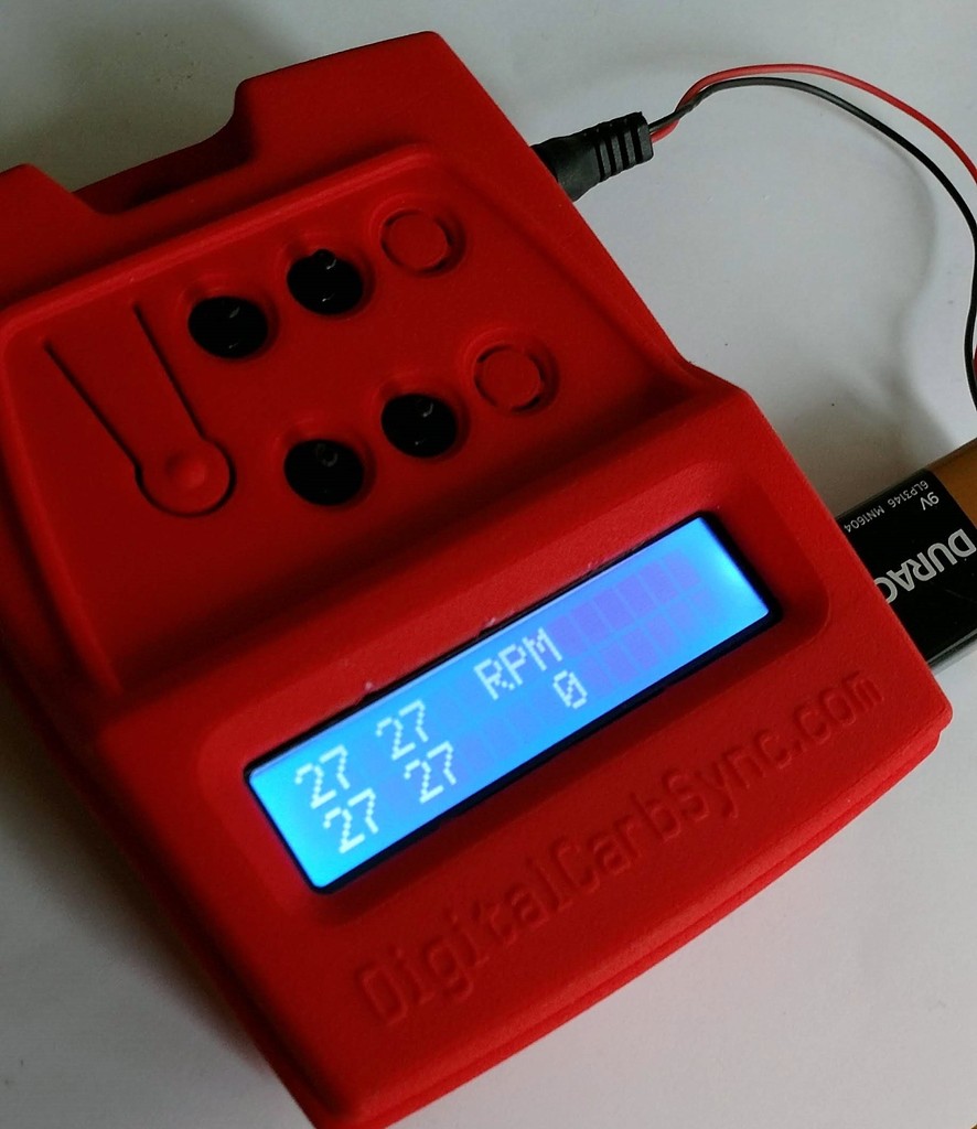
Digital is portable and clean

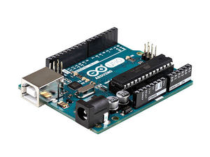
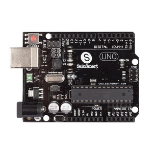
Digital units are lightweight and portable. Unfortunately, most are made for 2 cylinder engines. If you have 4 carb performance bike or something like a 6 carb Valkyrie or an old Kawasaki Z1300 or Honda CBX1000 things are more difficult and more expensive. Here’s a new and very expensive (~$350) example that only gets you 4 cylinders. There are also the usual fake mercury versions like the CarbTune.

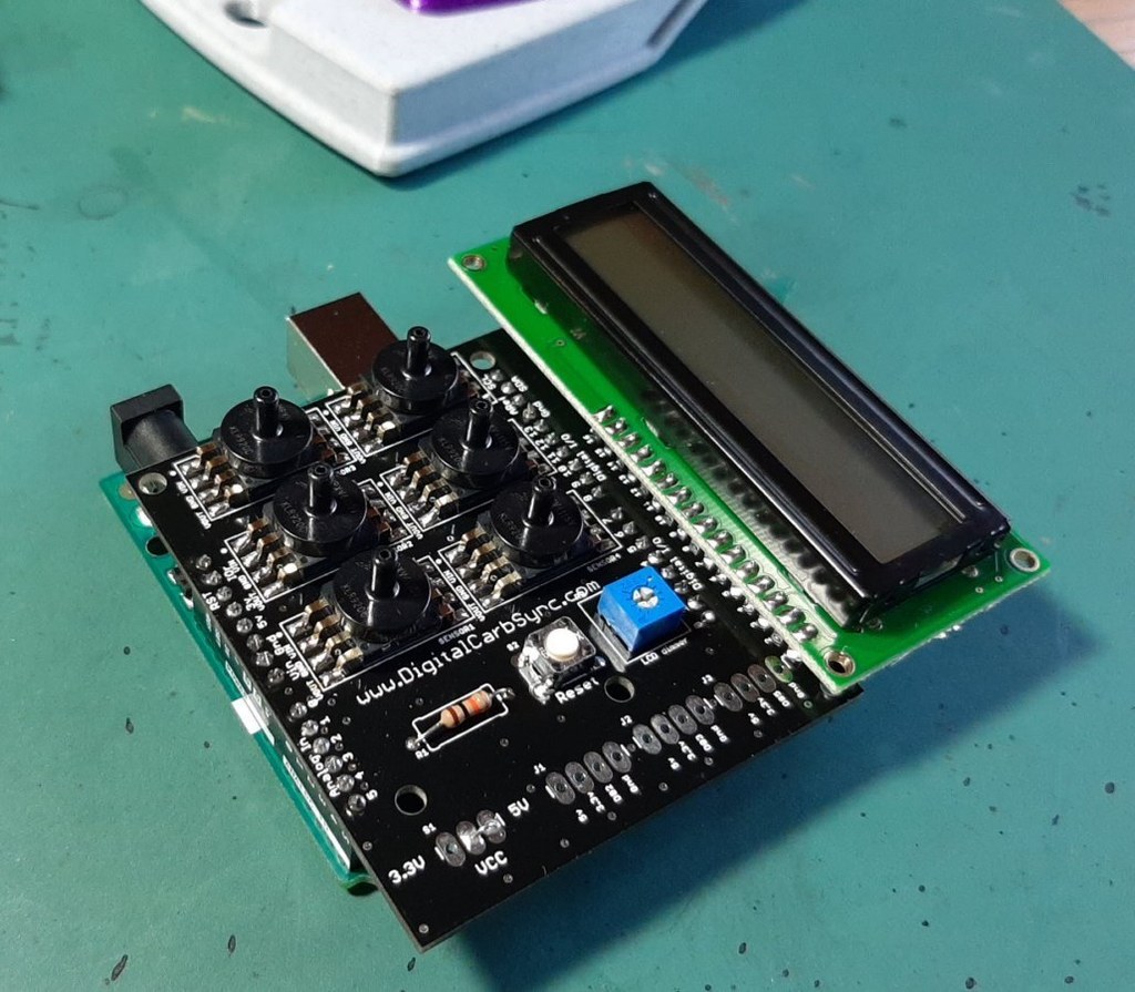
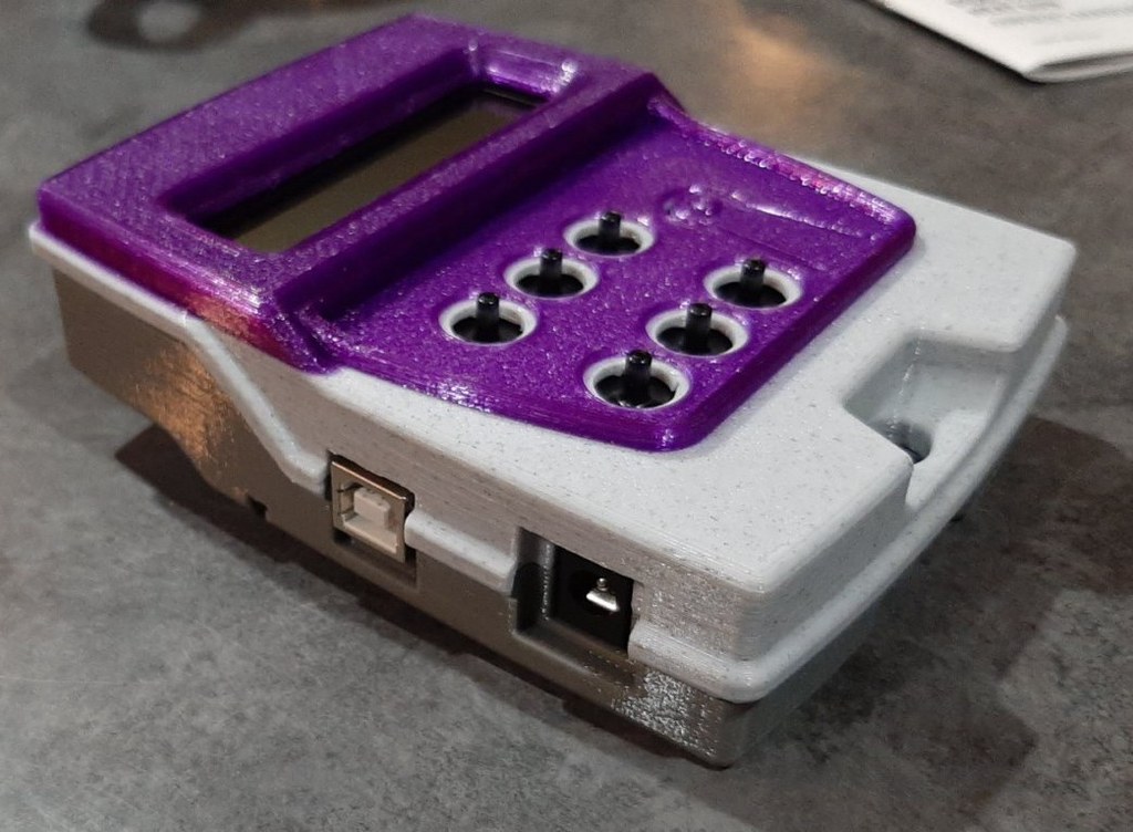
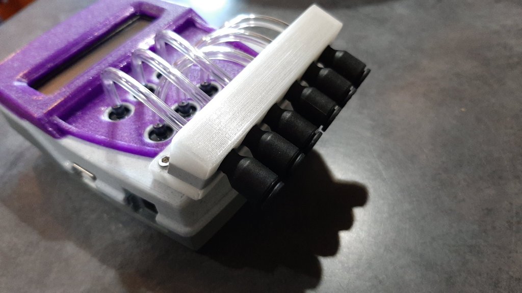
Building your own tools is real

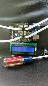
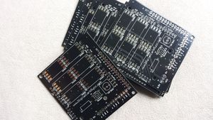
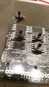
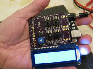
If you have basic shop skills and tools you can build the Digital Carb Sync in a couple of hours. Simple parts and basic soldering are all you need. Loading the software is easy, and the source code is available for people with some beginning code skills who want to make changes.

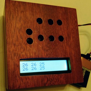
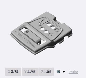
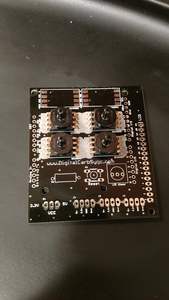
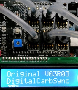
Digital Carb Sync kits are easy to build

Digital Carb Sync is the original design and kit that makes it easy to build your own digital carb sync tool. Get that bike running at its best. All you need is to download the build package to get started – our other items are for convenience. The Black Label boards and tubing connectors for your bike will save you time and money.

Digital Carb Sync Built for 4 cylinders
Posted on Leave a comment

Comments Post

I’ve got the schematic so I’m going to start working on the PCB, buy components and put everything together. Sometime soon I should be able to send you feedback on building the project. I thank You once again for providing the materials to me and the community, and I will keep You updated. Greetings from Germany! Darek.

Thanks for the effort you put into developing the Digital Carb Sync and providing it as a DIY project. I was able to fumble my way through the xloading process and it worked perfectly. You might put a plugin for Digi-Key for fast and accurate product ordering and shipping. Bruce S., Louisiana.

My friend the fancy box builder takes a run at a case! Salem, OR.


David sent this in.

I’m in Christchurch, United Kingdom (not Alabama!) 🙂

I have finally got my laser cut box design to a point where it might be useful to others.

https://www.thingiverse.com/thing:3623654

Rick did a nice job on his 6-cylinder build. He also used his 3-D printer with our plans to make a case. Then he added a quick release manifold. Well done!

Posted on Leave a comment

3-D Printed Cases

We have design files for 3-D printed cases for the Digital Carb Sync. They are easy to upload to a 3-D printer or printing service. Prices are dropping and you can find many reasonable options. A case is not needed but it looks nice and adds some protection to your device.

The designs are available for download in our catalog.

We sometimes have some samples available for sale for an easy way to add an optional case to your Digital Carb Sync device. Contact us using the form on the About page.

Below is a list of 3-D printing services we have used. There are many available around the globe. The materials available, and the cost, varies. Some offer color choices as part of the printing process. You can dye or paint the cases to your preference as needed. The red case in the photo is from Shapeways.

3-D printed in red
3-D printed in red
Posted on

Compatible Arduino Uno R3

Arduino Uno R3
Arduino Uno R3

Using the name brand product is the easiest.

You can find many less expensive substitutes. We see some as cheap as $5 on eBay. We have used them successfully when directly loading the HEX files.

Before buying a cheap board try to find out whether you will need a special driver on your PC. Make sure you get that driver or can get it if you need it.

If loading the HEX file on a cheap board gives you trouble as an alternative you can request, compile, and load the source software using the free Arduino IDE available free at https://www.arduino.cc/en/Main/Software. Use the downloadable version. Just copy the library folders included with the build package into the library folder of the IDE. Installing the IDE usually installs everything else you need including drivers for most boards.

See a range of options with this search on ‘compatible arduino uno r3‘.

SainSmart Uno R3
SainSmart Uno R3

Posted on

Manufacturing the boards

Black Label Board
Black Label Board

You can buy a board from us or make several of your own.

It is pretty cheap and easy to have boards made. Most places will accept online the gerber zip file included in the download package. Often you end up buying a multiple batch of some size but it is still inexpensive. The service we use sends 10 minimum. We buy the lead-free boards (often required in EU and other countries). Lead-free costs a bit more. You can order from any of the many board shops on the globe. You also can find many local board shops for less where you live.

We use https://www.seeedstudio.com/fusion_pcb.html

We buy the black lead-free board using the default options for the rest.

So, make your own, or buy one from us. Your choice will depend on shipping costs and whether you want more than one board.

Posted on

Uploading the Bill of Materials (BOM) to Digikey

It is easy to upload the BOM. It will be cheaper to buy the Uno elsewhere, and maybe the sensors. But this technique makes an easy one-stop shopping for all the parts. Follow these steps:

Create an account on Digikey.com.

Go to BOM manager and select upload an order.

Upload the BOM file. It’s an XLS spreadsheet file.

Select that info starts on row 2 during file interpretation.

Use the drop downs to match names of the first several columns. The Digikey part number is the first. Quantity 3 is the last one that needs to be matched.

Process the file. Make a cart.

Review the cart. Delete the items you are sourcing elsewhere (e.g. the Uno, the sensors).

You might find solder paste cheaper in your local electronics supply store, but for convenience, you can add this to your Digi-Key order: Solder paste at Digi-key

Posted on Leave a comment

Build instructions

  1. Make sure you have all the small parts, the circuit board, the Arduino or clone Uno, and the sensors you are going to use.

  2. The sensors have a notch in one corner. The board has a white dot near a corner of every pad. These align.

  3. If building with fewer than 6 sensors, mount using the two sensor locations on the left (1 & 4), then the two in the center (2 & 5). This aligns screen data and the sensors. Any other alignment requires custom software adjustments. For reference, the board is marked and the LCD is at the bottom.

  4. A little solder paste
    A little solder paste

    If using solder paste and either a hot plate or toaster oven put a dollop of paste on each pad, position sensors, heat carefully, then let cool. It is easy if you buy a small quantity of paste in a syringe dispenser. It is also easy to work with a small tub of paste and a small applicator. YouTube has solder paste videos – check them out. You don’t need a solder mask. It is highly recommended to use one of the solder paste methods on the sensors if you are new to soldering or don’t have a decent soldering iron.

    I'm Melting!
    I’m Melting!
  5. If using a soldering iron work carefully. YouTube has soldering videos – check them out.

  6. Do not proceed until you have the sensors mounted correctly with a quality solder job. Use a decent soldering iron, not a toy.

  7. Mount and solder the LCD dimmer potentiometer, the reset switch and the resistor. The pot and the reset only fit the board correctly. The resistor does not have a required polarity. Clip the excess leads off the resistor (and save to use in the next step).

  8. The board can use a short wire or an optional header and jumper to set the board sensor operating voltage. This only needs to be set once to match the voltage to the sensors being used. The board does not use IOREF so that a wider combination of Arduino’s and sensors can be supported. In most cases, sensors will run on 5v.

  9. Solder a solid wire from the small center hole to the small hole on the side (5v or 3.3v), or install the header and jumper. If you have a right angle header the long ends should point toward the edge of the board.

  10. The easiest way to solder the male pin headers for the Arduino mount is to place all four on the Arduino board. Fit the Carb Sync Shield board on top. This will hold everything in alignment. Then solder the header pins. If using breakaway headers size them correctly.

  11. The 3 small digital I/O headers locations are optional. If your kit has them it is recommended to leave them off. They connect to digital pins 2,3 and 5, ground and power. The middle one – J2 – is currently reserved for future use as the RPM sensor connector. J5 was reserved to switch off the calibration step in later versions of the software (v03r03+).

  12. There are many ways to connect the LCD display. The standard way is to solder a 16 pin male header up into the LCD. Take care to get it straight. Then push the long pins down through the shield board holes and solder. Take care to get it straight. It can be useful to solder both end pins first then check for alignment. That way it is easy to correct. This is a solid mount. You can use different 16 pin connectors to mount the LCD as desired. It can be removable, or right angle connected, or below the shield board level with the Arduino. Take care to get it straight.

  13. Most problems will be caused by failed solder joints at the header pins, sensors or LCD. Especially the LCD – it has many solder points to get right. Take care to do it right the first time. Be very certain the sensors are aligned correctly before soldering. Make sure the LCD is straight – use a jig or supports.

  14. Remember when you power it up the first time the potentiometer is a dimmer switch that you’ll have to adjust. A weak battery can cause random and mysterious problems.

  15. If something goes wrong most solder joints can be reworked. That is called reflowing the solder point. If something goes really wrong carefully de-solder the component to reposition. YouTube has lots of useful videos. Or find a friend with a better soldering setup than the one you used.

Posted on

Operating

  1. Follow the recommended carb sync method for your bike. These instructions assume that you know how to prepare and adjust your bike.

  2. The sensors have a 3mm port. A 1/8 inch ID tube works great. You will need a plastic reducing coupler to connect to a tube that fits your bike. Yamaha uses 5mm. A 3/16” ID tube works great. Honda uses a 6mm port. A 1/4” ID tube works great. Some makes and models vary. Make a set of tubes that are consistent. It doesn’t matter which size tube is longer but cut, build and hook-up everything the same.

  3. With your bike prepared for sync, hook up your tubes to the carbs and the sensors.

  4. With the bike NOT RUNNING connect the device to the dc power source you are using, or if it is already powered on, press the reset button.

  5. NOTE: new versions of the software do not use a calibration sequence. Wait for the calibration sequence to complete.

  6. It is normal for the calibration to set the sensor readout within a point or two of each other. If all sensors are reading the same that means someone did a really good job soldering it all together and everything is in ideal condition. For the rest of us, just note the relative settings when the bike is off. The Digital Carb Sync Shield is designed to be forgiving to build quality. New versions of the software do not use a calibration sequence. The software code can be adjusted if desired.

  7. START THE BIKE.

  8. Follow the bike’s owners manual to adjust the carbs.

  9. Get the readings as close to each other as you can. A few points difference is fine. The sensors are more accurate than needed.

  10. It is okay to open up the throttle but remember that if your vacuum advance is disconnected the bike may miss at higher RPMs.