-
Make sure you have all the small parts, the circuit board, the Arduino or clone Uno, and the sensors you are going to use.
-
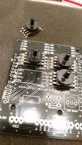
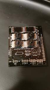
The sensors have a notch in one corner. The board has a white dot near a corner of every pad. These align.
-
If building with fewer than 6 sensors, mount using the two sensor locations on the left (1 & 4), then the two in the center (2 & 5). This aligns screen data and the sensors. Any other alignment requires custom software adjustments. For reference, the board is marked and the LCD is at the bottom.
-

A little solder paste If using solder paste and either a hot plate or toaster oven put a dollop of paste on each pad, position sensors, heat carefully, then let cool. It is easy if you buy a small quantity of paste in a syringe dispenser. It is also easy to work with a small tub of paste and a small applicator. YouTube has solder paste videos – check them out. You don’t need a solder mask. It is highly recommended to use one of the solder paste methods on the sensors if you are new to soldering or don’t have a decent soldering iron.
I’m Melting! -
If using a soldering iron work carefully. YouTube has soldering videos – check them out.
-
Do not proceed until you have the sensors mounted correctly with a quality solder job. Use a decent soldering iron, not a toy.
-
Mount and solder the LCD dimmer potentiometer, the reset switch and the resistor. The pot and the reset only fit the board correctly. The resistor does not have a required polarity. Clip the excess leads off the resistor (and save to use in the next step).
-
The board can use a short wire or an optional header and jumper to set the board sensor operating voltage. This only needs to be set once to match the voltage to the sensors being used. The board does not use IOREF so that a wider combination of Arduino’s and sensors can be supported. In most cases, sensors will run on 5v.
-
Solder a solid wire from the small center hole to the small hole on the side (5v or 3.3v), or install the header and jumper. If you have a right angle header the long ends should point toward the edge of the board.
-
The easiest way to solder the male pin headers for the Arduino mount is to place all four on the Arduino board. Fit the Carb Sync Shield board on top. This will hold everything in alignment. Then solder the header pins. If using breakaway headers size them correctly.
-
The 3 small digital I/O headers locations are optional. If your kit has them it is recommended to leave them off. They connect to digital pins 2,3 and 5, ground and power. The middle one – J2 – is currently reserved for future use as the RPM sensor connector. J5 was reserved to switch off the calibration step in later versions of the software (v03r03+).
-
There are many ways to connect the LCD display. The standard way is to solder a 16 pin male header up into the LCD. Take care to get it straight. Then push the long pins down through the shield board holes and solder. Take care to get it straight. It can be useful to solder both end pins first then check for alignment. That way it is easy to correct. This is a solid mount. You can use different 16 pin connectors to mount the LCD as desired. It can be removable, or right angle connected, or below the shield board level with the Arduino. Take care to get it straight.
-
Most problems will be caused by failed solder joints at the header pins, sensors or LCD. Especially the LCD – it has many solder points to get right. Take care to do it right the first time. Be very certain the sensors are aligned correctly before soldering. Make sure the LCD is straight – use a jig or supports.
-
Remember when you power it up the first time the potentiometer is a dimmer switch that you’ll have to adjust. A weak battery can cause random and mysterious problems.
-
If something goes wrong most solder joints can be reworked. That is called reflowing the solder point. If something goes really wrong carefully de-solder the component to reposition. YouTube has lots of useful videos. Or find a friend with a better soldering setup than the one you used.